CT/CJ Busbar Support Insulators: Stepped Creepage Design with Fixed Bar Spacing
Your busbars sit closer together every time a panel gets smaller, and the insulator holding them has to keep the surface path between phases long enough to stay safe. That is the design problem behind CT/CJ busbar support insulators: a stepped body that adds creepage distance without adding height, a single part that covers several mounting heights, and a fixed bar spacing that takes guesswork out of assembly. Here is how those features work, what to check before you specify them, and what your quote request should include.
Why Creepage Distance Drives Busbar Support Design
Creepage distance is the shortest path along an insulator’s surface between two conductive parts. It is a different number from clearance, which is the shortest path through air, and it fails in a different way: slowly, as moisture and dust build a conductive film on the surface and current starts to track across it. Under IEC 60664-1, the creepage you need depends on three inputs: the working voltage, the pollution degree of the installation environment, and the material’s group, which comes from its Comparative Tracking Index (CTI). Published worked examples put the minimum for 800 V DC at pollution degree 2 on a group IIIa material at about 8 mm, and the figure climbs as voltage, contamination, or tracking risk goes up.
In a compact panel that creates a squeeze. You can’t simply make the insulator taller, because the busbars have to stay where your layout puts them. So the shape of the insulator has to do the work.
How a Stepped Profile Lengthens the Surface Path
Creepage follows the surface, so any rib, groove, or step that the path must climb and descend adds length without adding straight-line height. That is why insulating parts are so often molded with ribs or steps: it is the standard way to lengthen the path between phases inside a fixed footprint.
There is a design rule behind this that your engineers will want to know. IEC 60664-1 counts a groove or step toward creepage when it is wide enough. At pollution degree 2 the minimum width is 1.0 mm, and anything narrower is treated as bridged, as if it were not there. That is why the dimensions of each step matter, not just the number of steps. Dust can also settle on horizontal steps, so in dirty enclosures the environment matters alongside the geometry.
What the CT/CJ Design Adds
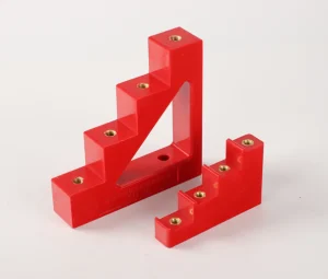
CT/CJ bus bar support insulators are molded from BMC/SMC and are used to support busbar systems at different heights in the same equipment, in single-phase, three-phase, and four-phase arrangements. The design adds four features on top of that:
- Large creepage distance design: the body is built around a long surface path between conductors, which gives you more margin against tracking and flashover in tight layouts.
- Stepped construction: the steps in the body increase the creepage distance without making the part taller.
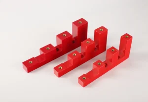
- One product, four heights: a single product satisfies four height requirements, so one part number covers layouts that would otherwise need several.
- Fixed bar spacing: the spacing between bars is set by the part rather than by the installer, which reduces human error during assembly.
Together, these cover what panel builders care about most in a busbar support: electrical safety margin, flexibility across layouts, and repeatable assembly. For your own panel, compare the stated creepage with the requirement for your working voltage and pollution degree.
Need more creepage distance without redesigning your panel?
CT/CJ Design Features and What to Verify
| Design Feature | What It Does | Check Against Your Design |
|---|---|---|
| Large creepage design with stepped body | Lengthens the surface path between phases without adding height | Creepage in mm for your voltage and pollution degree |
| Four heights in one product | Serves several mounting heights with one part number | Which of the four heights fits your layout |
| Fixed bar spacing | Sets phase-to-phase pitch at the part level | Spacing in mm against your copper bar layout |
| BMC/SMC material | Provides the insulating and mechanical base | CTI value, flammability rating, and applicable certifications |
Fixed Spacing and Height: Where Assembly Errors Come From
Most spacing errors happen at the bench, not in the design. When an installer sets phase-to-phase distance by hand with a ruler or loose spacers, small differences add up across a row of panels, and the tightest gap in the run is the one that sets your real clearance. A support that fixes the bar pitch removes that variable.
Height works the same way. The right height depends on the required clearance, the busbar thickness, and the layout of the box, which our guide to choosing the right busbar support insulator walks through. Mixing insulators of different heights in the same busbar run also shows up among the mistakes in our installation guide for distribution box busbar support insulators. A part that covers several heights helps you keep one run consistent without stocking a separate part number for each.
CT/CJ at a Glance
| Item | Detail |
|---|---|
| 材料 | BMC / SMC |
| Bus arrangements | Single-phase, three-phase, and four-phase |
| Typical use | Low-voltage distribution lines and communication lines |
| 申请 | Distribution boxes, switchgear, inverters, green power supply |
| 量 | 500 件 |
| 样本 | Free sample can be provided for bulk orders; sample lead time 3-7 days |
| Bulk lead time | 10-15 working days, depending on quantity |
| Customization | Large quantities can be customized with your logo (OEM) |
Where This Type of Support Fits
Frame-style supports like these suit equipment where several bars run side by side and at more than one height: distribution boxes, low-voltage switchgear, inverters, and green power supply cabinets. If you want a plain-language overview of the series before you get into specs, this explainer on what a CT insulator is and why it matters covers the basics.
What to Confirm Before You Specify
Our busbar support selection guide starts with your own copper bar specification, then the number of phases, the total number of bars, and the phase-to-phase distance between bars. Common spacings run from 55 mm to 180 mm, bars per phase can be single, double, three, or four rows, and the mounting screw hole size has to match your panel. Add the electrical side to that list: your working voltage, the pollution degree of the enclosure, and the CTI group of the material. With those inputs on hand, you can check the datasheet creepage against what IEC 60664-1 requires instead of taking a shape description on trust.
Have your bar layout and voltage ready? Get a quote built around them.
常见问题解答
How much creepage distance does my panel need?
It depends on your working voltage, the pollution degree of the enclosure, and the material’s CTI group under IEC 60664-1. Work out the required value for your own conditions, then compare it with the creepage stated on the insulator’s datasheet.
Does a stepped design collect more dust?
It can, because horizontal steps give dust somewhere to settle. In clean, enclosed panels this matters little. In dusty or humid environments, weigh the added path length against your inspection and cleaning routine.
Can one part really cover four heights?
Yes. A single CT/CJ product is designed to satisfy four height requirements, so one part number can serve layouts that would otherwise need several. Check which of the four heights matches your busbar layout when you send your inquiry.
How does fixed bar spacing reduce errors?
The part sets the pitch between bars, so installers no longer place each phase by eye or with loose spacers. Check that the fixed pitch matches your copper bar layout, since spacing options run from 55 mm to 180 mm.
Which phase arrangements are supported?
CT/CJ insulators support single-phase, three-phase, and four-phase buses.
Stepped creepage geometry, multi-height mounting, and fixed bar spacing each solve a different panel-building problem, but none of them replaces checking the numbers for your own design. Confirm the creepage value against your working voltage and pollution degree, confirm the heights and spacing against your copper bars, and approve a sample before you order in volume. That order of checks keeps surprises out of the production run. When you are ready, send us your bar layout and quantity.
Send us your bar layout and quantity.
Related Resources
- Combined Busbar Support Explained: A Complete Guide for Electrical Panels
- Understanding BMC / SMC Busbar Insulator Support: Material Properties and Performance
- Top Benefits of Using Standoff Busbar Support Insulators in Low-Voltage Systems
- Installation Guide for Distribution Box Busbar Support Insulators
- - 结尾 - -
 邮箱:
 东风市凌云路20号


 Chinese
 English (United States)
 English (South Africa)
 Arabic
 Belarusian
 Bengali
 Japanese
 Kazakh
 Korean
 Myanmar
 Russian
 Thai
 Ukrainian
 Uzbek
 Vietnamese